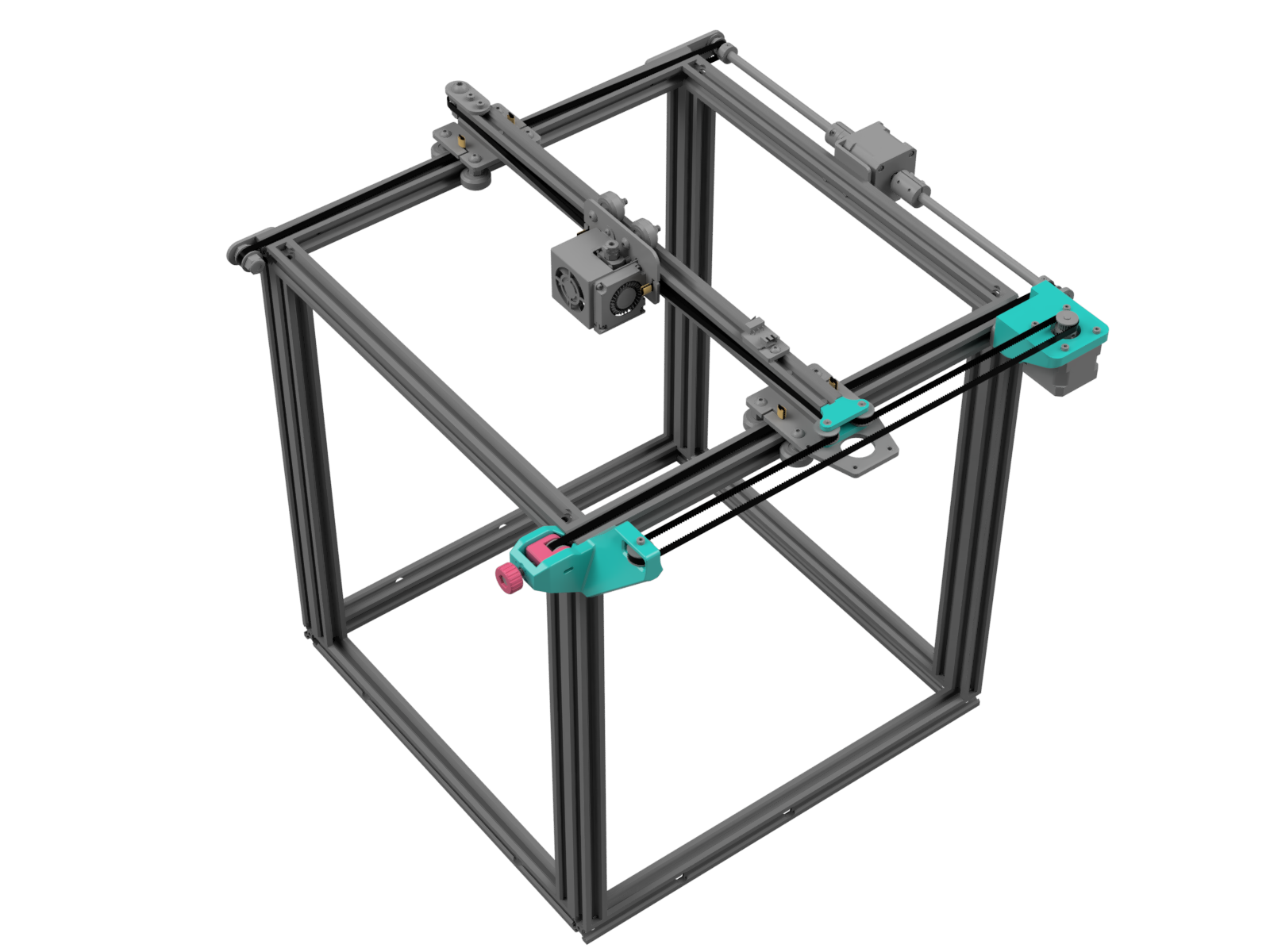
Stage 1: Hybrid CoreXY
The goal of this stage is to drop the heaviest single part on the X carriage: The stepper motor. This stage alone will remove almost half a pound of moving weight but only takes a few hours to print and assemble.
Bill Of Materials
Bolts
| Part | Type | Quantity |
|---|---|---|
| M3x12 socket head | ISO 4762, DIN 912 | 4 |
| M3x25 socket head | ISO 4762, DIN 912 | 4 |
| M5X25 hex head | ISO 4017, DIN 933 | 1 |
Washers
| Part | Type | Quantity |
|---|---|---|
| M3 | DIN 125 | 6 |
Hex Nuts
| Part | Type | Quantity |
|---|---|---|
| M3-0.5 hex nut | DIN 934 | 3 |
| M5-0.8 hex nut | DIN 985, ISO 10511 | 1 |
Belt
| Part | Size | Quantity | Link |
|---|---|---|---|
| GT2 belt | 6mm wide, 5m long | 1 | Amazon |
Pulleys
| Part | Size | Quantity | Link |
|---|---|---|---|
| GT2 toothless idler | 3mm bore, 20-tooth diameter | 5 | Amazon |
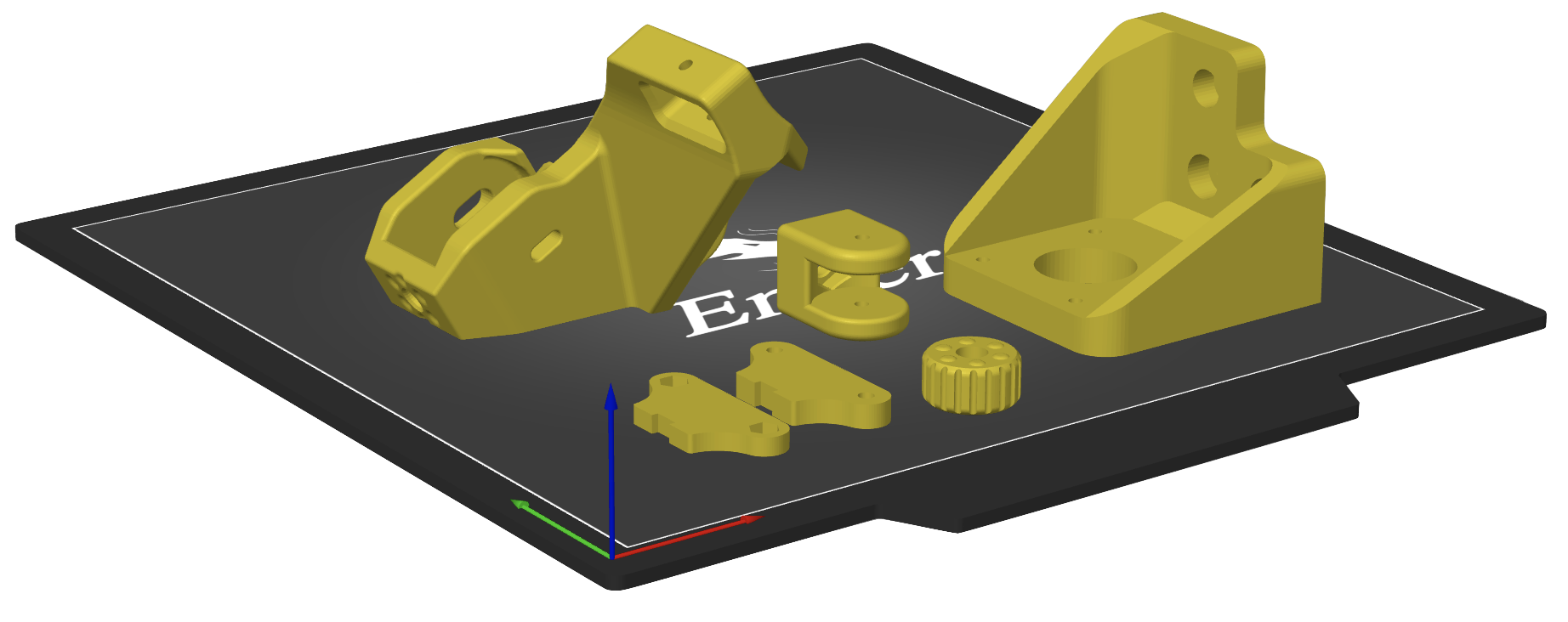
Printing
STL files for this stage are here
It should be easy to guess the print orientation for most of these parts. The only difficult one is the oddly-shaped front corner assembly. There’s one particularly flat face on the part that has no fillets on the corners; this is the face that was designed to be on the print bed.
You should use 100% infill for these parts and at least 4 perimeters/walls (for screw hole durability). Parts printed with 0.2mm layer height look fantastic but 0.24mm is several hours faster.
Front Corner Assembly
- Remove screws from front-right Y tensioner plate and set them aside for step 3
- Remove the screw from the tensioner keeping the Y belt captured
- Attach the front corner piece, reusing the M5 bolt and one of the M4 T-nut screws from the original plate on one side and the other M4 T-nut on the other corner of the aluminum extrusion
Front Pulleys
Next you’ll install the right Y belt tensioner and the X belt’s front pulley. If you bought the 5 pack of smooth pulleys linked in the BOM, you can use those both here and as the center pulleys.
- Hook the X belt onto a 20-tooth, 3mm bore pulley and slide it into place
- Add a washer to the top and bottom of the pulley
- Insert an M3x25 screw through the top and secure it onto the underside with a hex nut
- Insert the M5 hex nut into the hexagon slot on the inside of the Y belt tensioner and an M3 hex nut into the slot on the outer right side
- Hook the Y belt on another 20-tooth pulley and slide it into the tensioner housing
- (Optional) Add a washer on both sides of the pulley. This isn’t as critical as the other pulleys which are pulled into plastic due to gravity
- Place the tensioner housing inside the corner assembly and secure it into place with an M3x25 screw which will pass through housing and pulley and thread into the hex nut on the other side. The tensioner housing should now slide forward and back to tension the belt.
- Push the M5 bolt through the tensioner knob and thread it into the tensioner housing. Twist the knob until the right Y belt is as tight as the left.
Move The X Stepper
- Remove the screws on the back-right Y-axis pulley bracket and set aside
- Install the new stepper mount by on top of the old bracket, putting the screws back in the same places they were
- Remove the X stepper from the X gantry by removing the 4 screws on the top
- Move the stepper to its new mount and secure it with four M3x12 screws
Center Idlers
These two center idlers are the reason we’re using ones with a 3mm bore throughout the project rather than the more common 5mm bore. Because we’re making use of two of the stepper mounting holes on the original X stepper plate to hold the axles for the idlers. These holes are only large enough to use M3 screws as axles, hence the 3mm bore pulleys.
- Remove the old X belt if you haven’t already
- Place the bottom center idler block on top of the carriage (the bottom plate is the one without the hexagon holes)
- Sandwich two pulleys between washers and set them on top of the idler block
- Insert two M3 hex nuts into the top idler block and place on top of the pulleys
- Drive two M3x25 screws from the underside, passing through the holes original steel plate and then through our stack of new parts, finally threading into the hex nuts in the top center idler block
A Note On Washers
These little M3 washers can be tricky to install, and you may be tempted to skip them altogether. A good rule of thumb is anywhere that gravity is at play on a pulley, you’ll need a washer so it doesn’t rub. In short: Washers are going to be highly recommended on the X axis pulleys, but not so critical on the Y tensioners.
Optional Steps
Swap Motors
Highly Recommended
In the original Ender 5, the X stepper only needed to be strong enough to move the printhead. Now it will be sharing the weight of the entire carriage with the Y stepper (which you’ll notice is a bigger motor). This is why it’s highly recommended to swap the extruder stepper and the X stepper. This will allow you to reach higher speeds without skipping.
Tune Stepper Current
If you find that your X stepper motor is getting hot during long prints, you can turn your stepper current down a bit. Just follow this guide which should only take a few minutes to complete.
Stealthchop and Torque
Klipper Only
Stealthchop is a feature in many modern boards which quiets the stepper motor at the expense of slight inaccuracies and reduced torque. For maximum speeds, you would want to disable Stealthchop. Unfortunately the “silent” boards that come in the Ender 5 require some soldering to disable Stealthchop (look up “Creality 4.2.2 and 4.2.7 UART mod”).
That said, if you have a more modern board, you can disable Stealthchop for maximum torque while increasing your micro-steps to achive a very similar level of quiet from your steppers. Here’s what you would add to your printer.cfg (change “tmc2209” to your model’s stepper driver):
[stepper_x]
...
microsteps: 128
rotation_distance: 40

[tmc2209 stepper_x]
...
run_current: 0.620
interpolate: False

[stepper_y]
...
microsteps: 128
rotation_distance: 40

[tmc2209 stepper_y]
...
run_current: 0.650
interpolate: False
Troubleshooting
Height adjustments
Once you’ve installed and tightened your hybrid X belt you might notice that it’s not running perfectly parallel all the way along its path, or you might find that it’s slightly too high or low and it’s rubbing against the X rail after it passes through the center idlers. If this happens, there’s a number of adjustments you can make, depending on what the issue is.
- Raise/lower the pulley on the X motor (many but not all Ender 5 models have an adjustable grub screw on the pulley)
- Raise the center idlers with another washer
- Raise the front corner idler with another washer
Quacking Noise
Sometimes during printing, mainly on faster travel moves, you might hear a sound that’s reminiscent of an oversized goose honking. While it may seem like a mechanical issue (something rubbing, needing oil, etc.) it actually goes away completely when disabling StealthChop (see the StealthChop section above).