Stage 2: Linear Y Rails
The goal of this stage is to drop the next heaviest parts on the X carriage: The V-slot wheels and steel mounts. This will yield us another 270g of moving weight reduction–that’s another half pound!
Bill Of Materials
Linear Rails
Bolts
| Part | Type | Quantity | Link |
|---|---|---|---|
| M3x8 socket head | ISO 4762, DIN 912 | 20 | Amazon |
T-Nuts
| Size | Quantity | Link |
|---|---|---|
| M3 2020 T-nuts | 12 | Amazon |
Printing
STL files for this stage are here
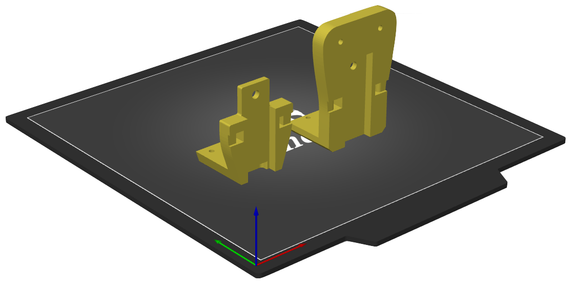
The right Y rail mount is best printed on its side, but you’ll need to make sure your bridge and support settings are dialed in pretty well to prevent sagging and any support interface being left behind (the tolerances for the aluminum extrusion are pretty tight on purpose).
The left mount can be printed in the same orientation or on its back. While this makes it easier to print and get correct tolerances against the aluminum extrusion, the strength at the belt attachment points is theoretically lower than being printed on the side.
A great help in mounting the rails is a rail alignment tool. There are several other similar alignment tools on Thingiverse and Printables if you don’t like this one. You’ll want to print this tool before beginning the next step.
Left Rail
- Loosen the X and Y belts then slide the Y belts out of the wheel plates. You won’t be able to reuse these belts so you can toss them.
- Remove the v-slot wheel screws and wheels on the left wheel plate
- Remove the two M5 screws on the underside of the plate which attach it to the X gantry and save these for later
- The plate can now be removed from the gantry
- Using M3x8 screws and T-nuts, secure the MGN12 rail to the outside of the frame (this is where the alignment tool comes in handy)
- Attach your new left linear mount (the smaller of the two) to the linear bearing block (the slidey thing) using M3x8 screws
- Press the X gantry into the 20mm cutout in the mount then use one of the M5 screws from step 3 to secure mount to the X gantry from the underside
- Fish one end of the Y belt through from the top of the new rail mount, then out the bottom and back in the direction it orginated
- Secure the belt against its own teeth using a zip tie or belt clip designed by the VzBot team.
Right Rail
- Remove the v-slot wheel screws and wheels on the right wheel plate
- Remove the two screws on the underside of the plate which attach it to the X gantry and save one of these screws for later
- The plate can now be removed from the gantry
- Remove the center idlers and the sandwich blocks. You won’t be needing the bottom block but the top one will be reused.
- Using M3x8 screws and T-nuts, attach the MGN12 rail to the outside of the frame (again, using the alignment tool)
- Attach your new right linear mount to the linear bearing block using M3x8 screws
- Press the X gantry into the 20mm cutout in the mount then use one of the M5 screws from step 2 to secure mount to the X gantry from the underside
- Reattach the center idlers as the were before, minus the bottom block. Don’t forget the M3 washers on both sides of the pulleys!
- Fish one end of the Y belt through from the top of the new rail mount, then out the bottom and back in the direction it orginated
- Secure the belt against its own teeth using a zip tie or belt clip
Optional Upgrades
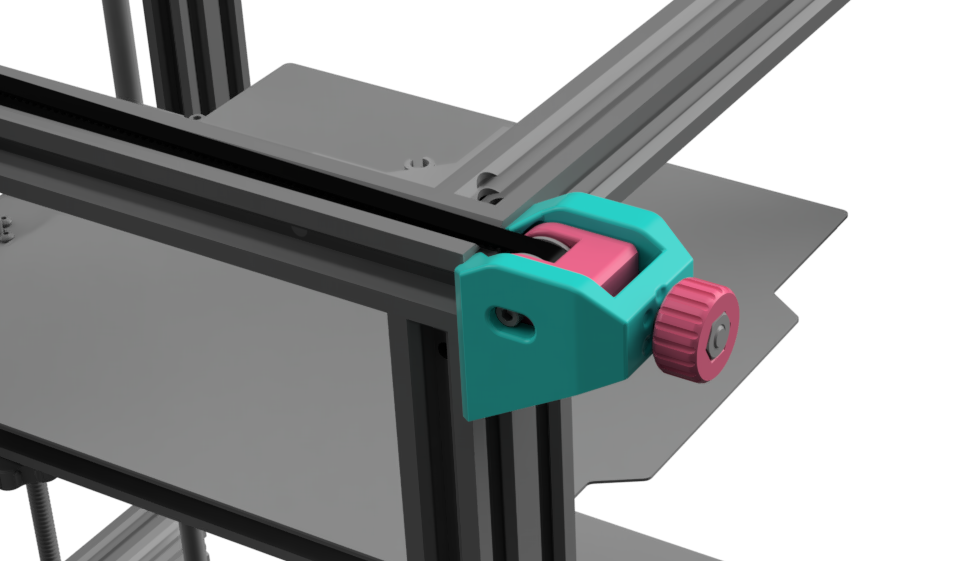
Left Y Tensioner
While your Y belts are off why not give yourself a nice modern tensioner on the left side like you have on the right?
The design is exactly the same as the right tensioner, so you just need to print a second knob and slider from stage 1 plus the tensioner housing. The hardware is also exactly the same as the right one (one M5x25 bolt and nut, one M3x25 screw and nut, and one 3mm pulley).
To secure it to the frame, just use one of the M4 T-nuts from the old tensioner. Assembly is the same as the right side.
X Tensioner
In addition to making belt tightening much easier and precise, this will also drop a bit more weight from the X gantry.
Assembly here is pretty straightforward. Remember when you saved the M5 screws from the wheel plates? Well, because those M5 threads were cut all the way through the extrusion, we can reuse that hole to secure our X tensioner from the top! It will be held from wobbling on side-to-side by the lower peg that slots right into your left Y rail block.
The rest of the parts (the slider, knob, and hardware) are the same as the other tensioners. You’ll just need to print the main housing here then assemble it like the others.
Plating
There’s a flatter side near the back to make printing easier. The auto-orient feature of many slicers should pick the right side. If your overhang/cooling settings are dialed in you might not even need support!
